Primitive Curves
Nodes for creating fundamental curve geometry - lines, arcs, circles, rectangles, tangents, and freeform splines.
31 nodes in this group
Lines & Polylines
Straight-line geometry defined by endpoints or geometric constraints. Lines are the simplest curve type and the most common starting point for parametric models.
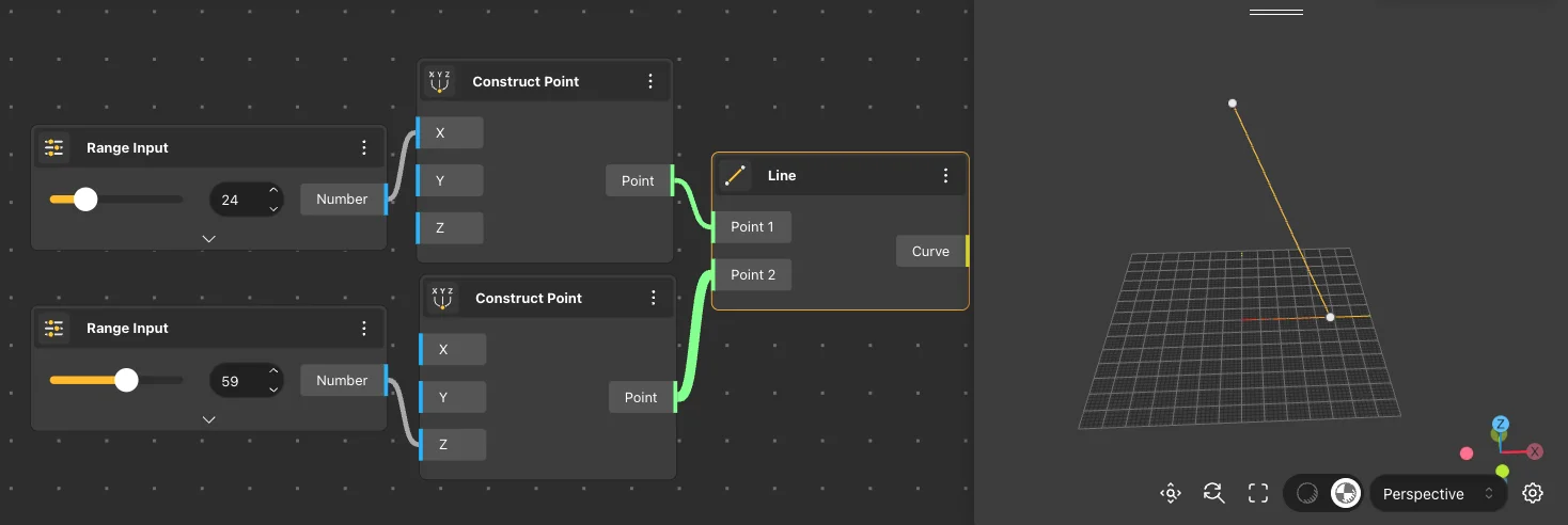
Line
Behavior
Creates a straight line segment between two points in 3D space. Default: Start {0,0,0} → End {1,0,0}. Outputs a single Curve. If Start and End are identical, outputs a zero-length curve. Accepts lists - produces one line per point pair using the active list matching mode.
Inputs
Start Point, End Point
Outputs
Curve
Pairs With
Extrude Curve, Offset Curve, Linear Array
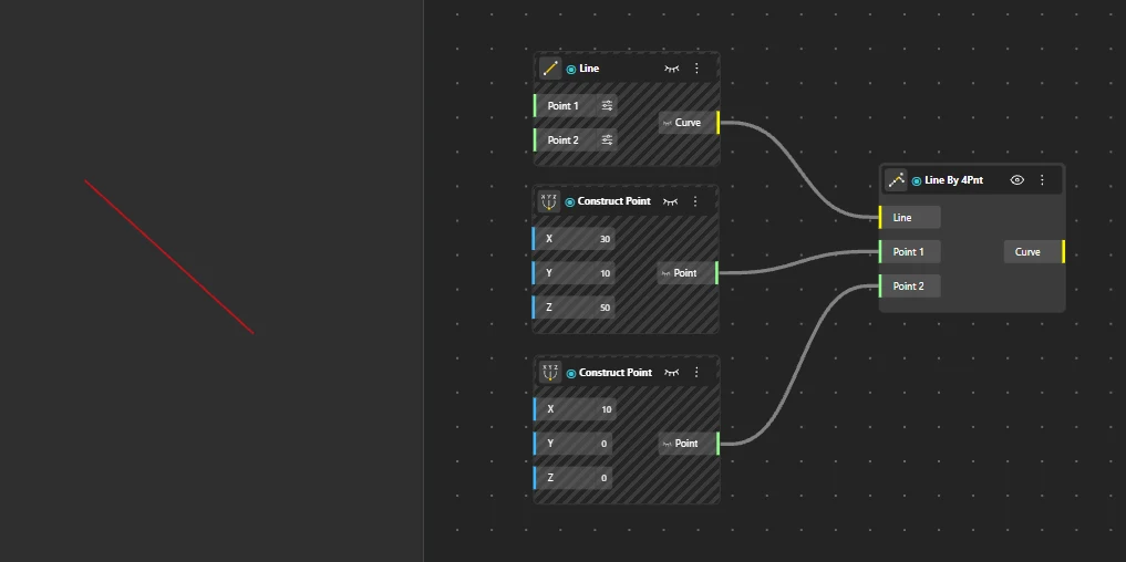
Line by 4 Points
Behavior
Creates a line derived from two point pairs - computes the geometric relationship between two line segments defined by (P1,P2) and (P3,P4). Requires all four points. Output depends on the spatial configuration of the two pairs. The resulting line represents the intersection or closest approach between the two implied line segments.
Inputs
Point 1, Point 2, Point 3, Point 4
Outputs
Curve
Pairs With
Construct Point, Intersection 2 Curve
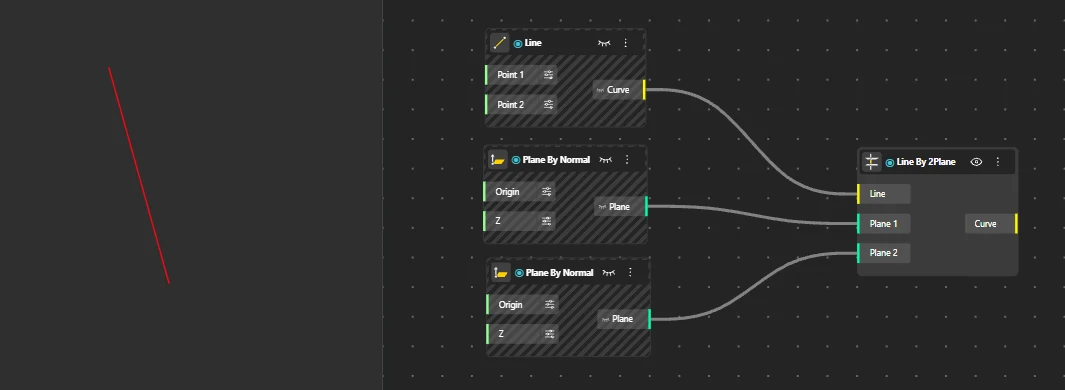
Line by 2 Planes
Behavior
Creates a line at the intersection of two planes. The resulting line lies on both planes simultaneously. Requires two non-parallel planes. Parallel planes produce no output. The output line extends infinitely along the intersection direction. If the planes are parallel (no intersection exists), the node returns an empty result.
Inputs
Plane A, Plane B
Outputs
Curve
Pairs With
Construct Plane, Plane XY, Plane XZ
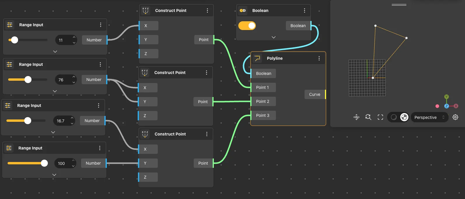
Polyline
Behavior
Creates a multi-segment line by connecting a sequence of points in order. Optionally closes the shape by connecting the last point back to the first. Close: false. Minimum 2 points required. Points are connected in list order. When Close is true, an additional segment is added from the last point to the first. A single point produces no curve.
Inputs
Points, Close
Outputs
Curve
Pairs With
Construct Point, Curve To Surface, Extrude Curve
Splines & Smooth Curves
Smooth and freeform curves driven by control points, interpolation, or blending. Used to define organic profiles, lofted surfaces, and complex parametric shapes.
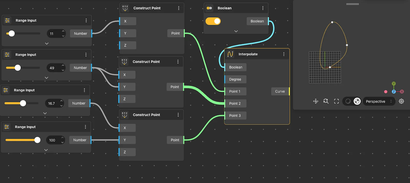
Interpolate
Behavior
Creates a smooth curve that passes directly through every given point. The curve is guaranteed to touch each input point. Minimum 2 points. The curve passes through all points in list order. Unlike NURBS Curve, the output always intersects the input points. The degree of smoothness depends on point spacing - closely spaced points produce tighter curvature.
Inputs
Points
Outputs
Curve
Pairs With
Divide By Count, Loft Surface, Pipe
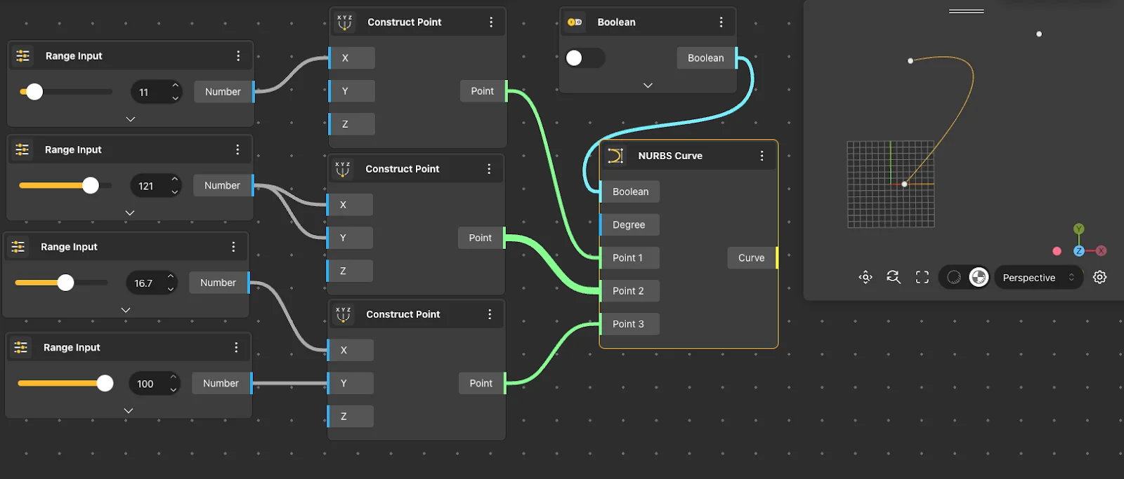
NURBS Curve
Behavior
Creates a NURBS curve using control points. The curve is attracted to control points but does not necessarily pass through them - producing smoother, more predictable shapes. Minimum 2 control points. Degree is determined automatically from point count. Control points act as weighted attractors. Moving one control point affects the curve locally, not globally. More control points allow finer shape control but increase complexity.
Inputs
Control Points
Outputs
Curve
Pairs With
Control Points, Revolve Surface, Sweep2
NURBS Curve PwkD
Behavior
Creates a NURBS curve with explicit control over points, weights, knots, and degree. Full parametric access to the underlying NURBS representation. Requires matching list lengths for points and weights. Knot vector length must equal points + degree + 1. Weights control how strongly each control point attracts the curve - higher weight pulls the curve closer. Invalid knot/weight combinations produce no output.
Inputs
Points, Weights, Knots, Degree
Outputs
Curve
Pairs With
Control Points, List Sequence
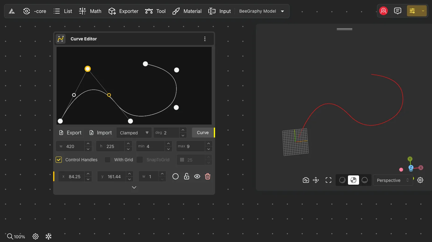
Curve Editor
Behavior
Returns a NURBS curve built from control points, degree, and curve type configured directly in the node's input field. Double-click the input field to add a new control point. Click between existing points to insert; toggle between smooth and sharp by clicking the circle/rectangle indicator next to each point. An optional grid with snapping helps align points precisely.
Inputs
Control Points (in-node editor), Degree, Curve Type
Outputs
Curve
Pairs With
Loft Surface, Sweep2, Pipe
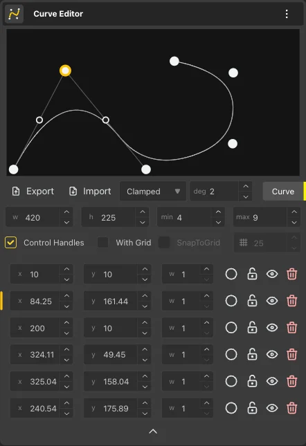
Click between two existing points to reveal small markers, then double-click one to insert a new control point at that location.
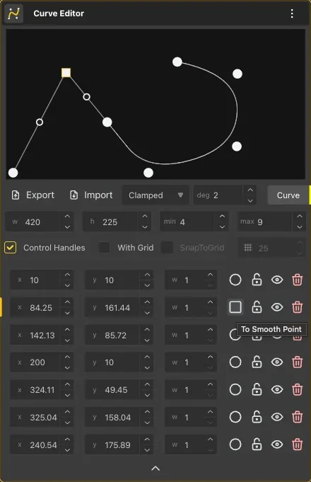
Click the circle next to a point in the list to make it sharp; click the rectangle to make it smooth again.
Tween Curve
Behavior
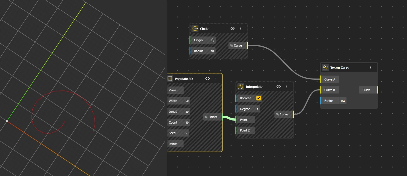
Generates an intermediate curve between two input curves at a specified parameter (0 to 1). At 0 it matches Curve A, at 1 it matches Curve B, values in between produce a morphed blend. Parameter: 0.5 (midpoint between the two curves). Both input curves should have the same number of control points for predictable morphing. Mismatched curves may produce unexpected intermediate shapes.
Inputs
Curve A, Curve B, Parameter
Outputs
Curve
Pairs With
Range Input, Loft Surface, Linear Array
Blend Curve
Behavior
Creates a smooth transition curve that blends between the endpoints of two existing curves with tangent continuity. Connects the end of Curve A to the start of Curve B with G1 tangent continuity. The blend maintains the tangent direction of both input curves at the connection points. If curves are far apart, the blend stretches to bridge the gap.
Inputs
Curve A, Curve B
Outputs
Curve
Pairs With
Join, End Points
Circles & Ellipses
Closed conic curves defined by a center and radii. The foundation for circular profiles, holes, and rotational construction.
Circle
Behavior
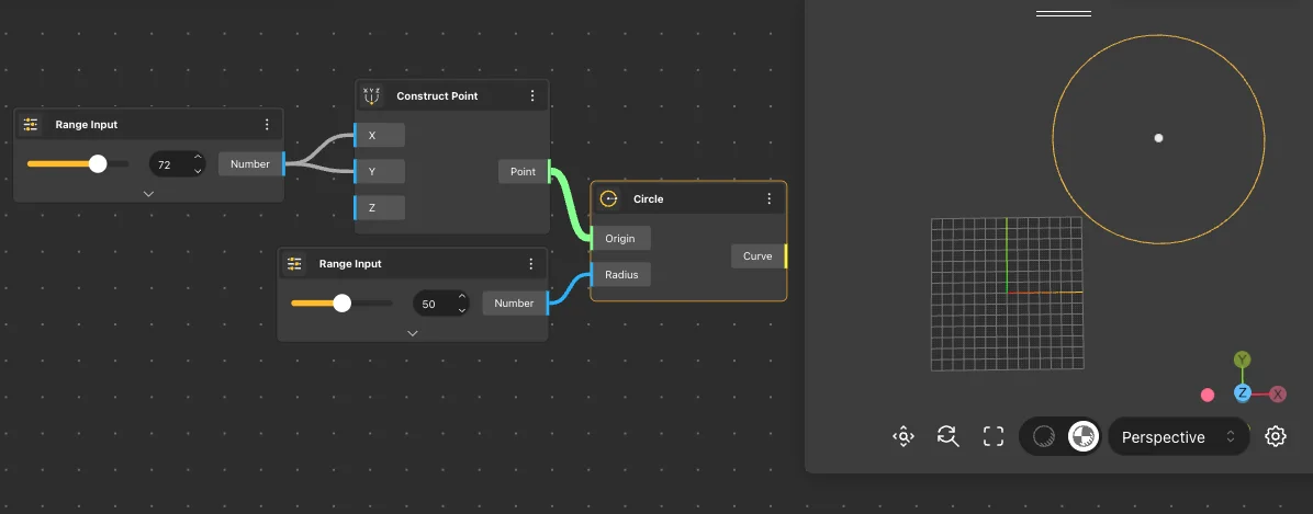
Creates a circle from a center point and radius on a specified orientation plane. Center: {0,0,0}. Radius: 1. Plane: XY (if not connected). The Plane input controls the circle's orientation in 3D space. Without a plane connection, the circle lies flat on XY. The output is a closed curve.
Inputs
Center, Radius, Plane
Outputs
Curve
Pairs With
Extrude Surface, Pipe, Polar Array
Circle 3Pnt
Behavior
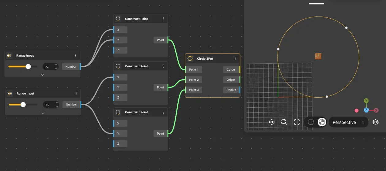
Creates a circle that passes through exactly three specified points. Center and radius are computed automatically. Requires 3 non-collinear points. If the three points are collinear, the circle cannot be computed and returns no output. The circle's plane is determined by the three points.
Inputs
Point 1, Point 2, Point 3
Outputs
Curve
Pairs With
Construct Point, Curve To Surface
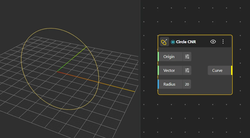
Circle CNR
Behavior
Creates a circle defined by center, a normal vector for orientation, and radius. The normal vector controls which direction the circle faces. Normal: {0,0,1} (facing up). The circle plane is perpendicular to the normal. Unlike Circle which takes a Plane input, this accepts a Vector - easier to orient circles using geometry normals from surfaces or faces.
Inputs
Center, Normal, Radius
Outputs
Curve
Pairs With
Face Normal, Unit Vector
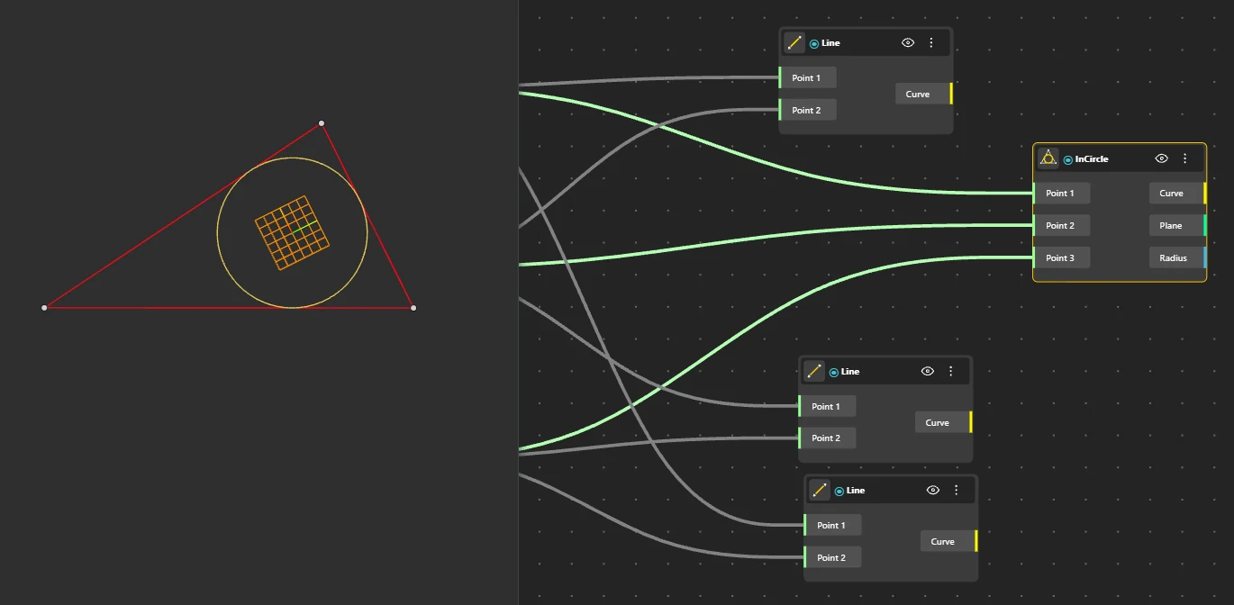
Incircle
Behavior
Creates the largest circle that fits inside a triangle defined by three points. The incircle is tangent to all three edges. Requires 3 non-collinear points forming a valid triangle. Outputs the circle, its center (incenter), and the computed radius. Degenerate triangles (zero area) produce no output.
Inputs
Point 1, Point 2, Point 3
Outputs
Curve, Center, Radius
Pairs With
Delaunay Mesh, Triangle Panel
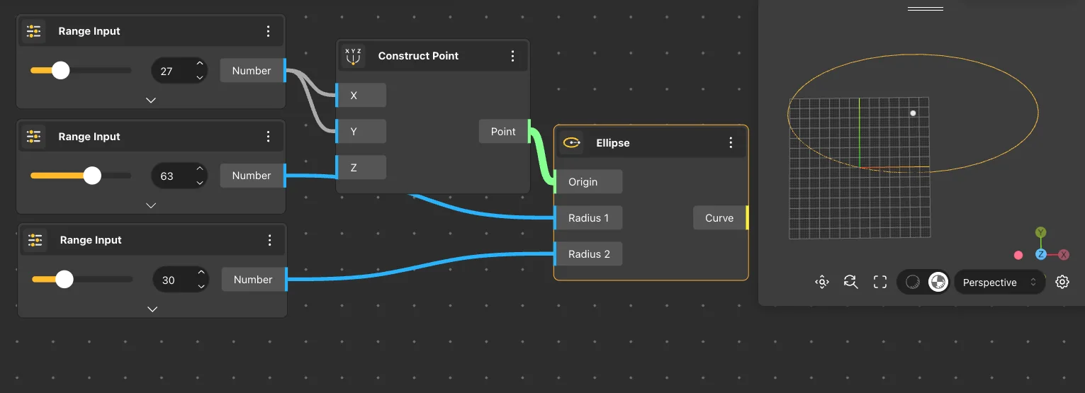
Ellipse
Behavior
Creates an ellipse from a center point with independently adjustable major and minor radii. Center: {0,0,0}. Major R and Minor R both default to 1 (producing a circle). When Major R equals Minor R, the output is identical to a Circle. The ellipse lies on the XY plane by default. Output is a closed curve.
Inputs
Center, Major R, Minor R
Outputs
Curve
Pairs With
Loft Surface, Extrude Surface
Tangents
Construct lines and arcs that meet circles tangentially. Used for fillets, smooth transitions, and geometric constructions.
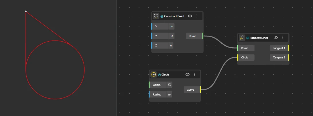
Tangent Lines
Behavior
Creates tangent lines from an external point to a circle. Returns the two possible tangent lines touching the circle at one point each. Requires a point outside the circle. A point inside the circle produces no tangent. Always produces exactly two tangent lines for a point outside the circle. If the point is on the circle, produces one tangent line.
Inputs
Point, Circle
Outputs
Tangent Lines
Pairs With
Circle, Join
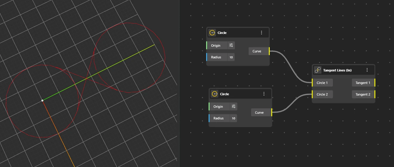
Tangent Lines (In)
Behavior
Creates internal tangent lines between two circles - lines that cross between the circles, touching each at one point. Requires two non-overlapping circles. Internal tangents cross the line connecting the two centers. If circles overlap, internal tangents do not exist and the node returns no output.
Inputs
Circle A, Circle B
Outputs
Tangent Lines
Pairs With
Circle, Distance 2 Points
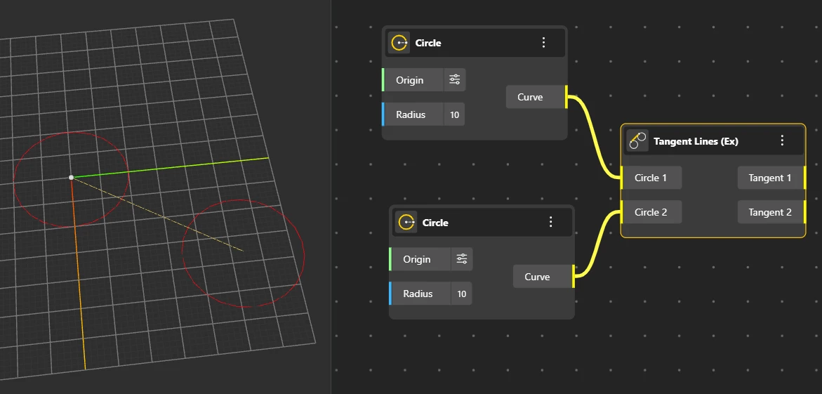
Tangent Lines (Ex)
Behavior
Creates external tangent lines between two circles - lines that touch each circle on the outside without crossing between them. Requires two circles that are not concentric (different centers). External tangents exist for any two non-concentric circles, even if they overlap. Concentric circles (same center) have no tangent lines.
Inputs
Circle A, Circle B
Outputs
Tangent Lines
Pairs With
Circle, Join
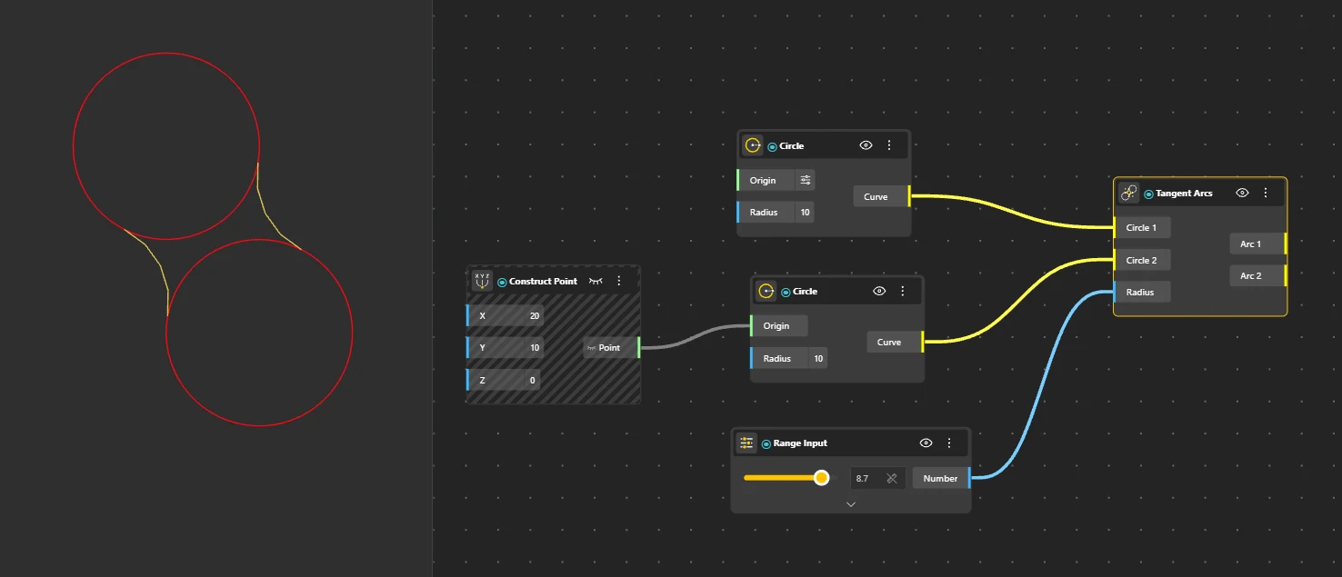
Tangent Arcs
Behavior
Creates arc segments that are tangent to two existing circles - smooth curved connections with a specified fillet radius. Requires two circles and a fillet radius large enough to bridge both circles. The output arc smoothly connects two circles with tangent continuity at both contact points. If the radius is too small to reach both circles, no arc is produced.
Inputs
Circle A, Circle B, Radius
Outputs
Arc
Pairs With
Circle, Fillet Geometry
Arcs
Partial circular arcs defined by points, angles, or directions. Used for fillets, sweeps, and curved profiles.
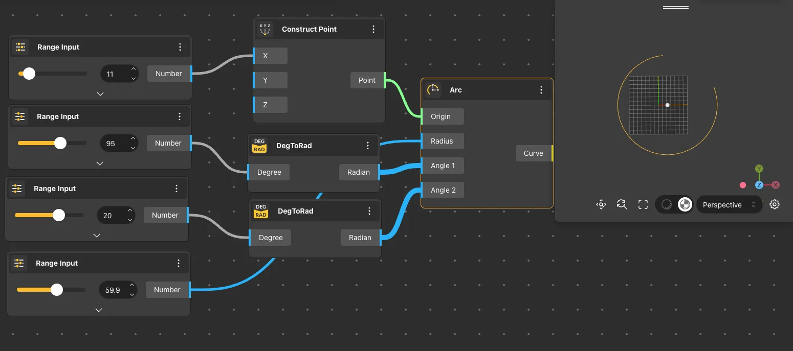
Arc
Behavior
Creates an arc from a center point, radius, and sweep angle. The arc sweeps counter-clockwise from the starting direction. Center: {0,0,0}. Radius: 1. Angle: in radians (use DegToRad to convert). An angle of 2π (360°) produces a full circle. Negative angles sweep clockwise. The arc lies on the XY plane by default.
Inputs
Center, Radius, Angle
Outputs
Curve
Pairs With
DegToRad, Revolve Surface
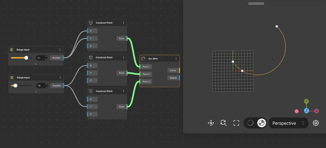
Arc 3Pnt
Behavior
Creates an arc that passes through three specified points - start, a point on the arc, and end. Requires 3 non-collinear points. The mid point controls the curvature direction - it determines which side of the start-end line the arc bows toward. Collinear points produce a straight line.
Inputs
Start, Mid, End
Outputs
Curve
Pairs With
Point On Curve, End Points
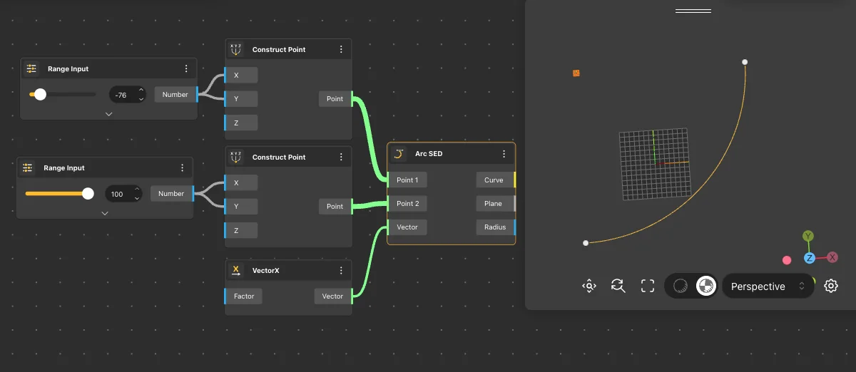
Arc SED
Behavior
Creates an arc defined by start point, end point, and a direction vector at the start. The vector controls the initial tangent. Direction vector determines the arc's departure angle from the start point. The arc leaves the start point in the direction of the vector, then curves to meet the end point. Vector magnitude does not affect curvature - only direction matters.
Inputs
Start, End, Direction
Outputs
Curve
Pairs With
VectorXYZ, Join
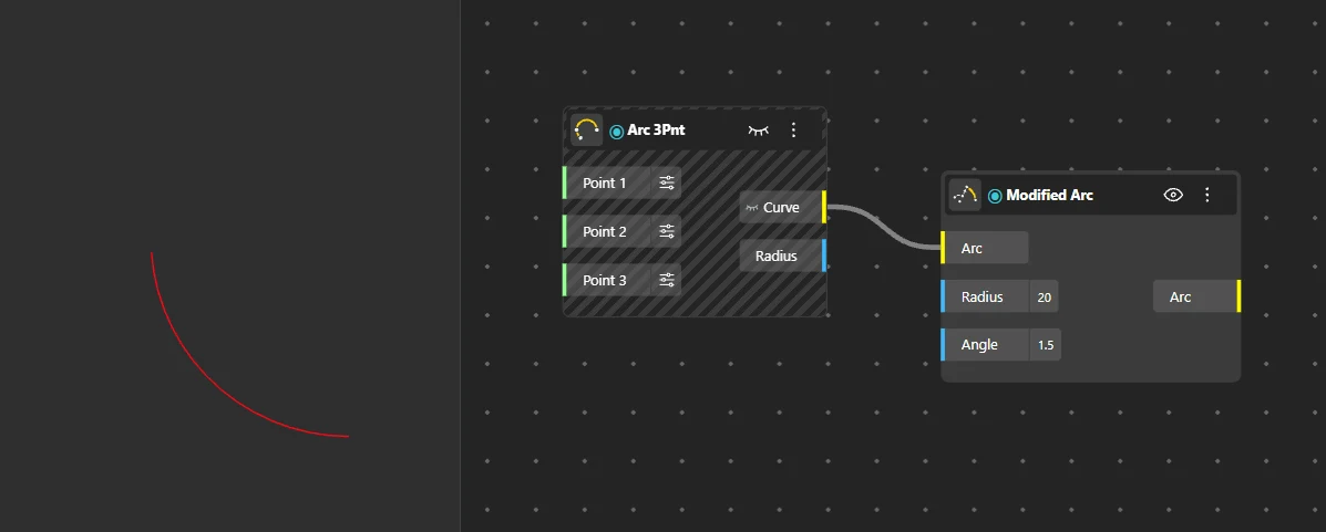
Modified Arc
Behavior
Creates an arc with additional modification parameters - provides extra control over curvature beyond center/radius/angle. Modifier: 0 (no modification, behaves like standard Arc). The modifier parameter adjusts the arc's shape beyond standard construction. Values away from 0 deform the arc progressively.
Inputs
Center, Radius, Angle, Modifier
Outputs
Curve
Pairs With
Range Input, Loft Surface
Rectangles
Closed four-sided profiles for panels, plates, and rectangular cuts. Multiple constructors fit different design intents.
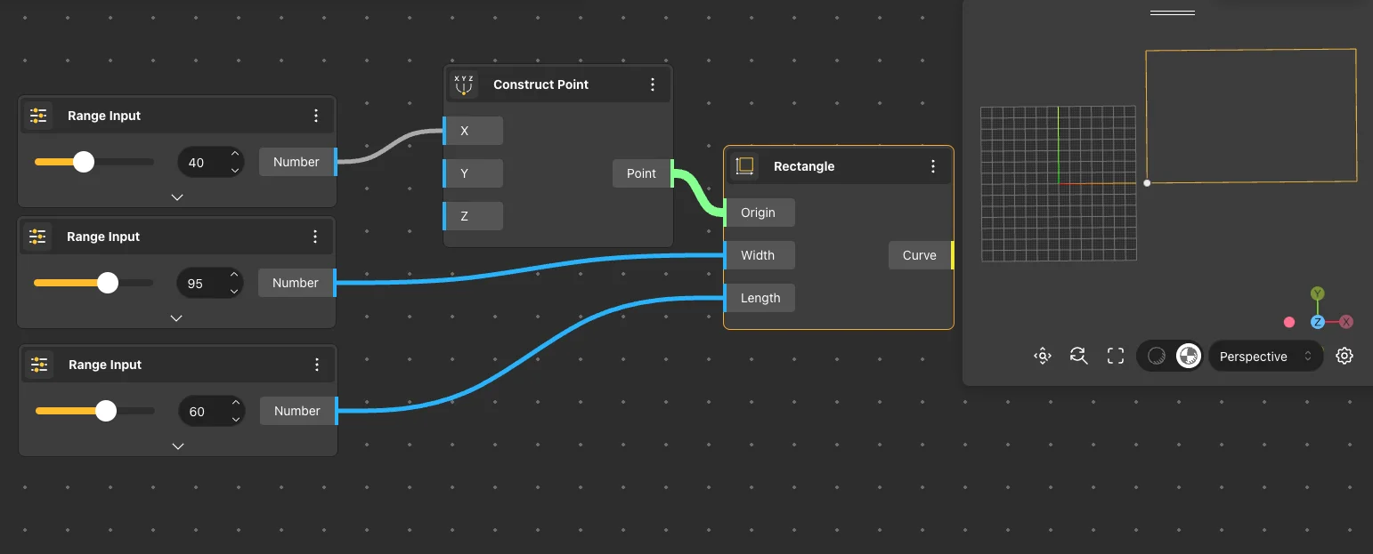
Rectangle
Behavior
Creates a rectangle from an origin point (bottom-left corner) with specified width and height. Origin: {0,0,0}. Width: 1. Height: 1. Output is a closed curve. The rectangle extends in the positive X (width) and Y (height) directions from the origin.
Inputs
Origin, Width, Height
Outputs
Curve
Pairs With
Curve To Surface, Extrude Surface, Offset Curve
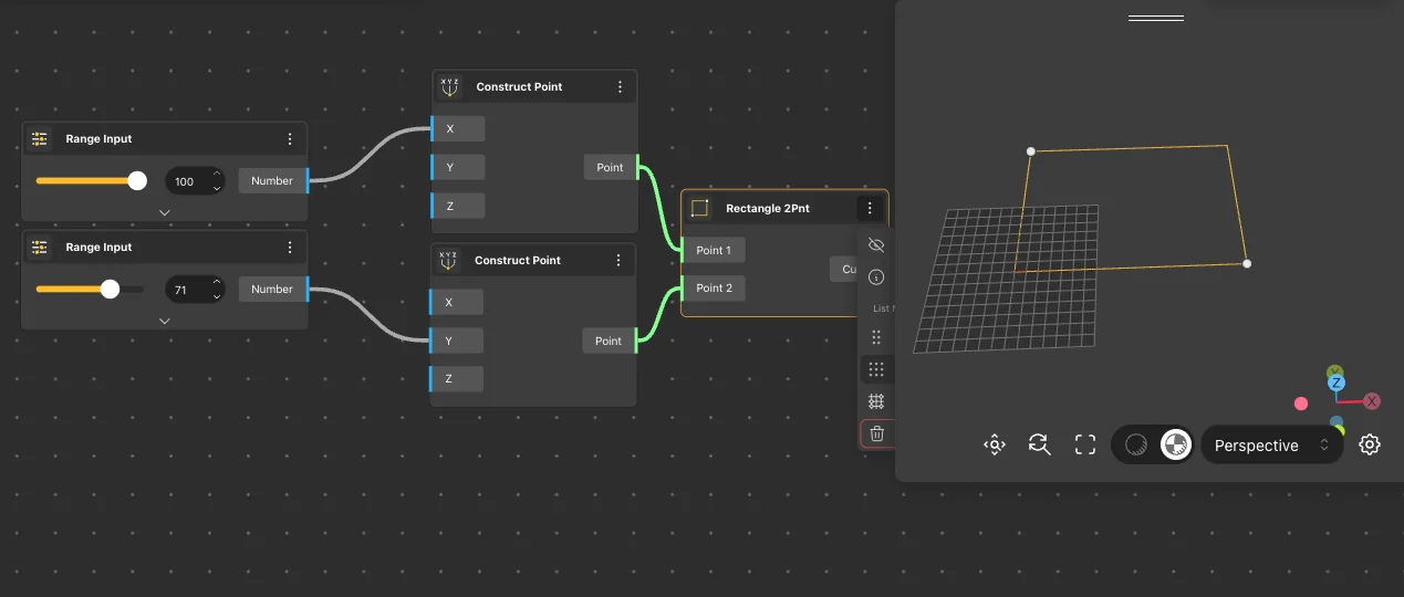
Rectangle 2Pnt
Behavior
Creates a rectangle defined by two diagonal corner points. Width and height are computed from the point positions. The two points define opposite corners of the rectangle. The rectangle aligns to the XY plane. If both points share the same X or Y coordinate, the rectangle collapses into a line.
Inputs
Point A, Point B
Outputs
Curve
Pairs With
Bounding Box, Extremes
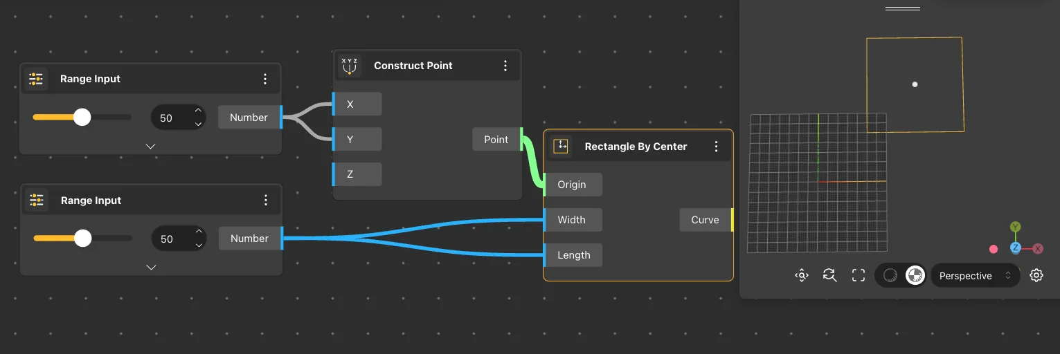
Rectangle By Center
Behavior
Creates a rectangle centered on a given point, expanding equally in all directions by half the width and height. Center: {0,0,0}. Width: 1. Height: 1. The center point is the geometric center of the rectangle, not a corner. The rectangle extends ±width/2 and ±height/2 from center.
Inputs
Center, Width, Height
Outputs
Curve
Pairs With
Centroid, Rectangular Array
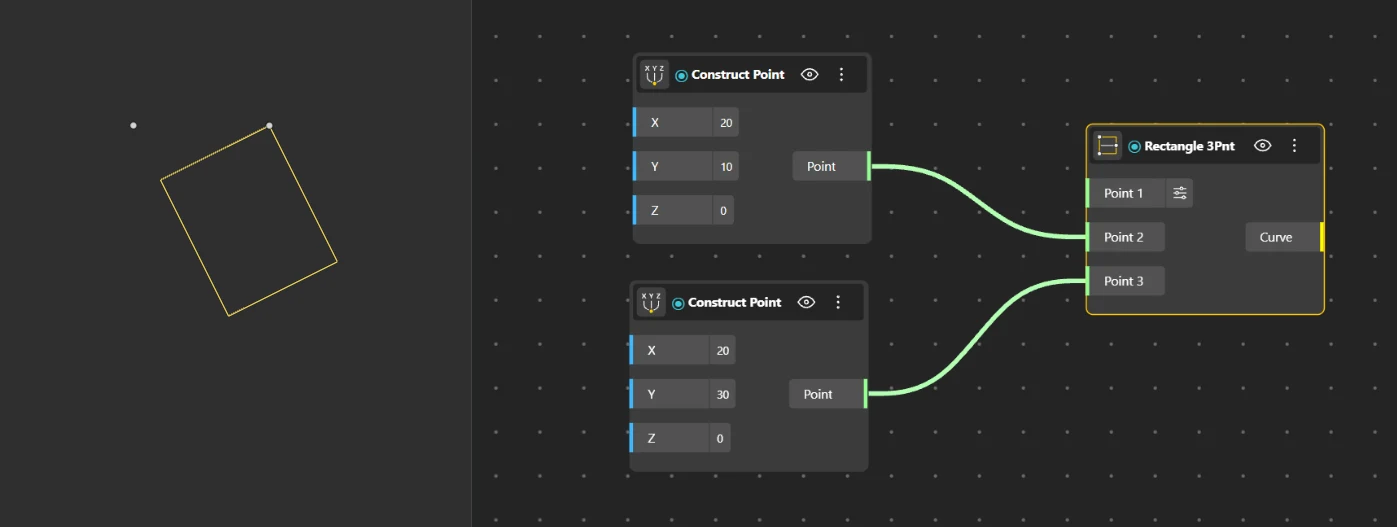
Rectangle 3Pnt
Behavior
Creates a rectangle defined by three points - two points define one edge, the third defines the perpendicular extent. Points 1-2 define the base edge. Point 3 sets the height perpendicular to that edge. The rectangle aligns to the direction of the base edge (P1→P2), not to the global axes. This allows creating rectangles at arbitrary angles.
Inputs
Point 1, Point 2, Point 3
Outputs
Curve
Pairs With
Construct Point, Curve To Surface
Polygons
Regular polygons and stars built from a center, radius, and side or vertex count.
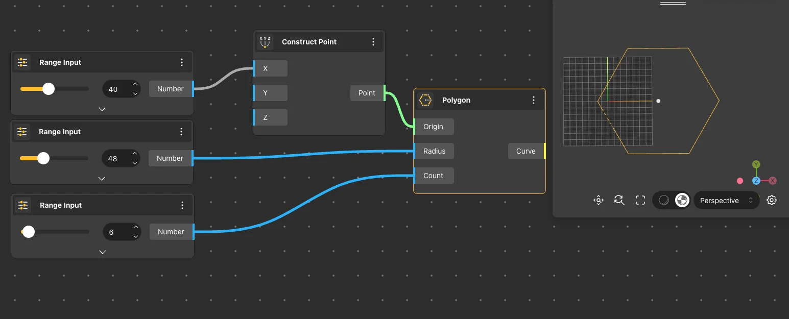
Polygon
Behavior
Creates a regular polygon with a specified number of sides inscribed in a circle of the given radius. Center: {0,0,0}. Radius: 1. Sides: 6 (hexagon). All sides are equal length and all angles are equal. Sides = 3 produces a triangle, 4 a square, 6 a hexagon. Output is a closed curve.
Inputs
Center, Radius, Sides
Outputs
Curve
Pairs With
Hexagonal Grid, Polar Array, Extrude Surface
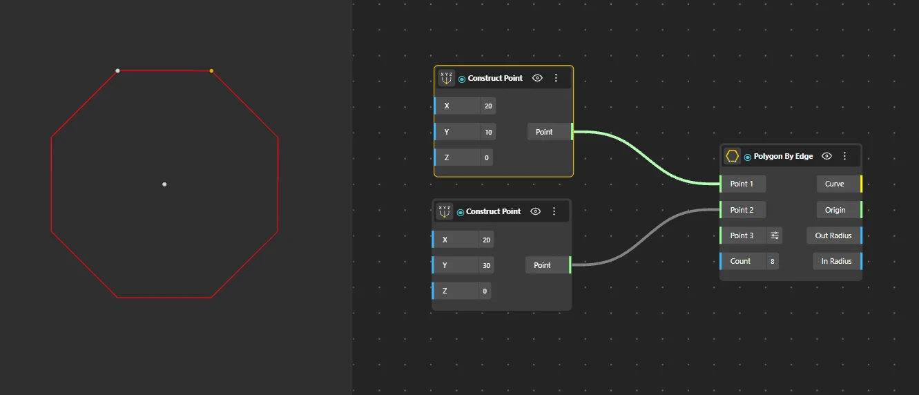
Polygon by Edge
Behavior
Creates a regular polygon defined by one edge (two points) and the number of sides. The polygon is constructed outward from the given edge. The edge length is determined by the distance between Point A and Point B. Unlike Polygon (which uses a radius), this constructs from a known edge length. The polygon builds outward perpendicular to the edge direction.
Inputs
Point A, Point B, Sides
Outputs
Curve
Pairs With
End Points, Explode
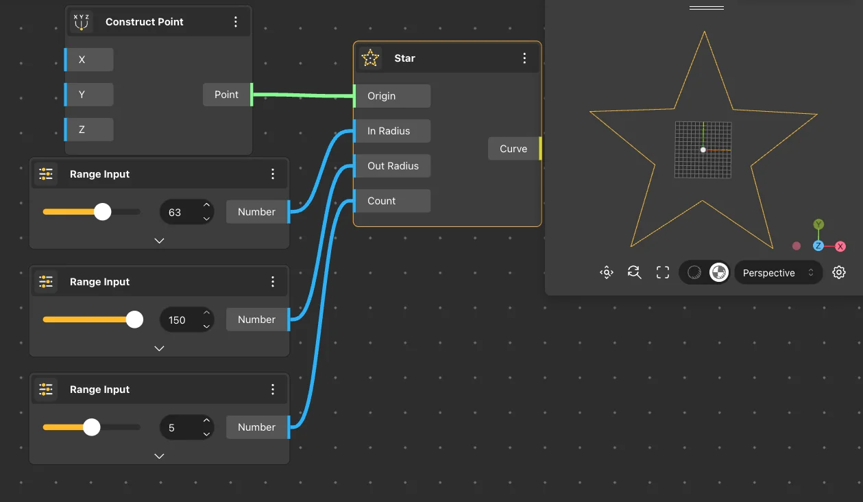
Star
Behavior
Creates a star shape with alternating inner and outer radii. The number of points controls how many tips the star has. Center: {0,0,0}. Outer R: 1. Inner R: 0.5. Points: 5. Inner R controls the depth of indentations between tips. When Inner R equals Outer R, the output becomes a regular polygon. Output is a closed curve.
Inputs
Center, Outer R, Inner R, Points
Outputs
Curve
Pairs With
Extrude Surface, Polar Array
3D Curves
Three-dimensional curves that extend beyond the XY plane. Used for spiral profiles, threads, and sweeping rails.
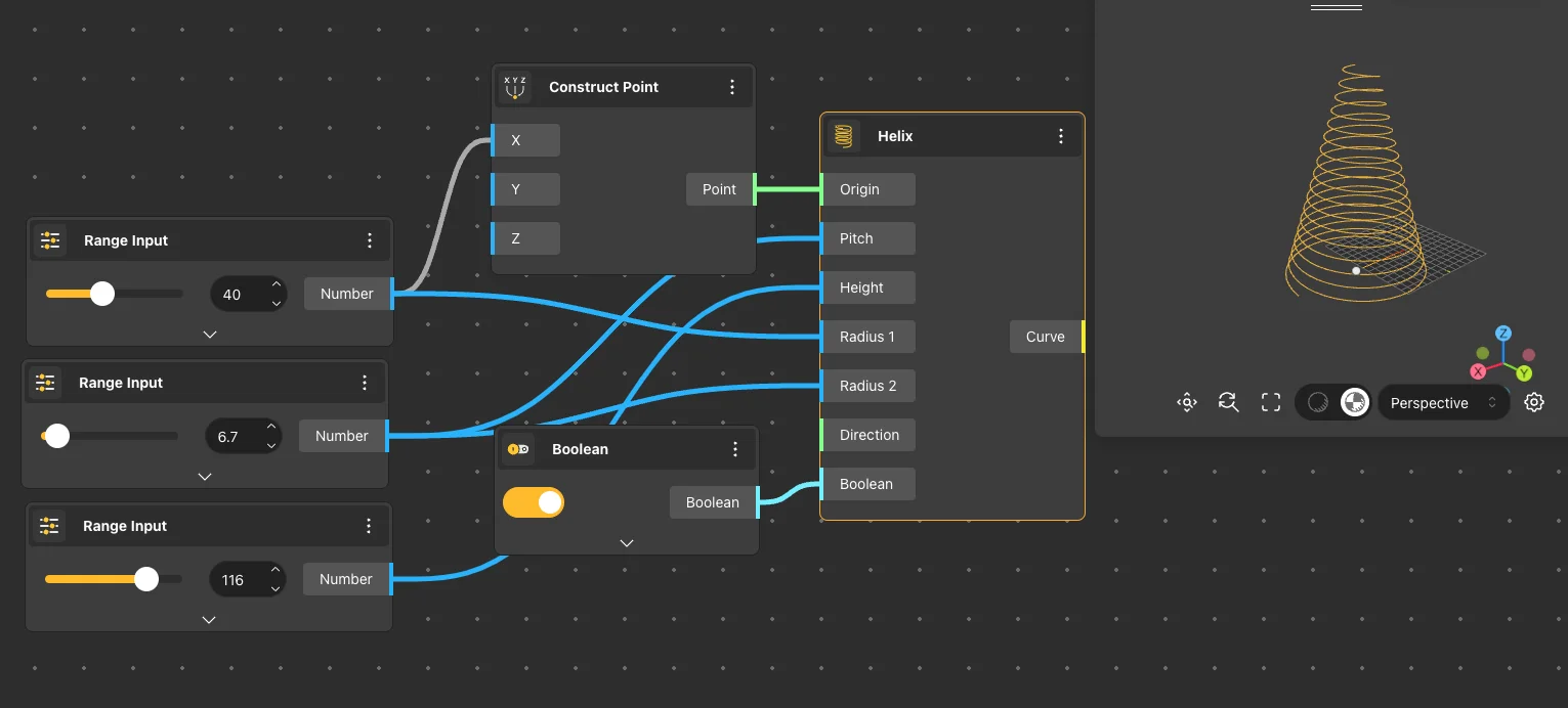
Helix
Behavior
Creates a 3D helical spiral curve with specified radius, pitch (vertical distance per turn), and number of turns. Radius: 1. Pitch: 1. Turns: 3. The helix spirals along the Z axis. Total height = pitch × turns. Increasing turns at constant pitch makes the helix taller. This is one of the few primitive curves that produces 3D geometry by default.
Inputs
Radius, Pitch, Turns
Outputs
Curve
Pairs With
Pipe, Curve Array, Sweep2